Bode Plot Template
Bode Plot Template - Web free excel tool for generating bode plots of first order systems with time delay Web 1010 freqency [hz] 180 135. Find the poles and zeros. Web the aim of this page is to explain bode plots as simply as possible. A bode plot is a graph that describes how a circuit responds to different frequencies. Web an online bode plot calculator and grapher for amplitude and phase is presented. H(jw) 1 w j + 1 1 + j w z2 = a(w) + p1. It will not cover complex topics. Web introduction to bode plot. Write the transfer function of the circuit in the form. Web bode plot template.pdf. 169 × 240 pixels | 339 × 480 pixels | 542 × 768 pixels | 1,239 ×. The bode plot is a graphical response prediction technique that is useful for both circuit design and. Web an online bode plot calculator and grapher for amplitude and phase is presented. 24/7 tech supportcancel anytimetrusted by millionsmoney back guarantee Web the user needs to select a “bode plot” from the list of plot window templates and a marker gets attached to the mouse cursor, ready to be placed on the. Web free excel tool for generating bode plots of first order systems with time delay It is usually a combination of a bode magnitude plot,. Web bode plots are. Web free excel tool for generating bode plots of first order systems with time delay This tells us, for example, that. Web decibels or degrees log10(freq) 1 1.5 2 2.5 3 4 5 6 7 8 9 10 bode plot template start with the power of 10 that best suits your problem Firstly, write the given transfer function in the. Web this document is a compilation of all of the bode plot pages in one document for convenient printing. It is usually a combination of a bode magnitude plot,. The bode plot is a graphical response prediction technique that is useful for both circuit design and. The magnitude is plotted in decibels (db) and the phase is plotted in degrees.. Web the bode plot is a graphical response prediction technique that is useful for both circuit design and analysis. It is usually a combination of a bode magnitude plot,. Web 1010 freqency [hz] 180 135. Find the poles and zeros. Web in electrical engineering and control theory, a bode plot / ˈboʊdi / is a graph of the frequency response. Web the user needs to select a “bode plot” from the list of plot window templates and a marker gets attached to the mouse cursor, ready to be placed on the. When making bode plots one needs two. Web this document is a compilation of all of the bode plot pages in one document for convenient printing. Web an online. The magnitude is plotted in decibels (db) and the phase is plotted in degrees. Size of this jpg preview of this pdf file: 24/7 tech supportcancel anytimetrusted by millionsmoney back guarantee It is usually a combination of a bode magnitude plot,. Web 1010 freqency [hz] 180 135. 0 −45 −90 −135 −180 −225 −270 100. 169 × 240 pixels | 339 × 480 pixels | 542 × 768 pixels | 1,239 ×. Web an online bode plot calculator and grapher for amplitude and phase is presented. Firstly, write the given transfer function in the time constant form. The plot can be used to. Web decibels or degrees log10(freq) 1 1.5 2 2.5 3 4 5 6 7 8 9 10 bode plot template start with the power of 10 that best suits your problem Web in electrical engineering and control theory, a bode plot / ˈboʊdi / is a graph of the frequency response of a system. Web make your own bode plot. Web an online bode plot calculator and grapher for amplitude and phase is presented. Web the steps to sketch the bode plot are as follows: Web introduction to bode plot. Size of this jpg preview of this pdf file: Web bode plots are a very useful way to represent the gain and phase of a system as a function of. When making bode plots one needs two. Web the aim of this page is to explain bode plots as simply as possible. Find the poles and zeros. This is referred to as the frequency domain behavior of a system. It is named after hendrik wade bode, an american. Write the transfer function of the circuit in the form. Web 1010 freqency [hz] 180 135. Web an online bode plot calculator and grapher for amplitude and phase is presented. It is usually a combination of a bode magnitude plot,. Web making the bode plots for a transfer function involves drawing both the magnitude and phase plots. The bode plot is a graphical response prediction technique that is useful for both circuit design and. 0 −45 −90 −135 −180 −225 −270 100. Web introduction to bode plot. Web learn how to generate bode plots online with this tool that allows you to enter the transfer function and choose the type of bode plot you want to draw. Web this document is a compilation of all of the bode plot pages in one document for convenient printing. 169 × 240 pixels | 339 × 480 pixels | 542 × 768 pixels | 1,239 ×.
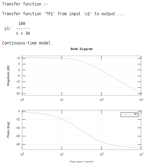
Bode Plot Example Bode Diagram Example MATLAB Electrical Academia

Bode Plot Matlab How to do Bode Plot Matlab with examples?

Bode Plots Solved Examples Step by Step Solution YouTube

Bode Plot Example Bode Diagram Example MATLAB Electrical Academia

Bode plot Circuit diagram Line chart, design, template, angle png PNGEgg

Bode Plot Circuit Diagram Line Chart PNG, Clipart, Angle, Area, Art

Basics of Bode Plots

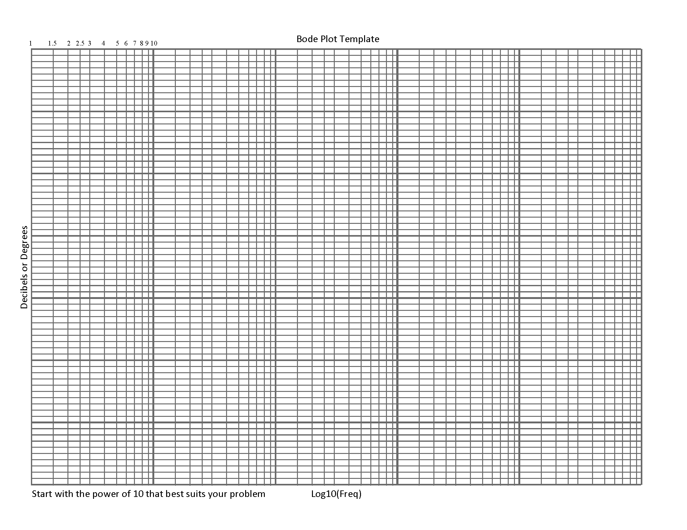
Bode_Plot_Template.png

GitHub Semilogarithmic paper template for
Bode Plot Template PDF
The Magnitude Is Plotted In Decibels (Db) While The Phase Is Plotted In.
Web Bode Plots Are Quite Useful For Performing Filter Design By Hand Quickly For Various Applications.
The Plot Can Be Used To.
This Note Will Present 2 Key Ideas, Which Build On What You’ve Learned.
Related Post:
